

Limited feasibility study of the Wind Energizer (WE) Concept by Leviathan Energy
The WE promises to increase power output from a wind turbine (WT) as it deflects and “energizes” the flow ahead of the WT, see http://leviathanenergy.com/technology/leviathan-wind/.
Vorcat, Inc. performed a preliminary study that demonstrated the efficacy of the concept. In addition, placing a second WT directly behind another unit was found to be impractical due to strong blockage.
A sketch of the setup modeled is shown below (wind direction is from right to left):
The Tasks:
Place two WEs as sketched in a row.
Compute the Available Wind Power Gain (AWPG) in the rotor plane

where Uz is the streetwise velocity, UZ,0 is the unperturbed axial wind velocity (P is the available wind power).
The Grid:


Closeup of Wind Energizers
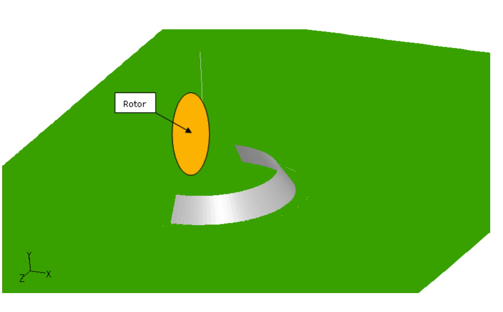
Rotor Model
based on GE 1.5 MW turbine:
3 blades per rotor
vortons released at tips only
induction ratio a = Vi/V∞.
For simplicity both rotors are assumed to experience the identical a=1/2.
Tip speed ratio (Xtsr) connects blade movement to simulation time. For simplicity Xtsr=10 (normally determined from empirical power coefficient).
Results:
Flow with two-rotors over fully inviscid geometry:
Isolates front rotor wake flow contribution to the power drop at rear rotor
Serves ONLY as a test case to rotor flow model compared to experimental and/or design parameters.
Flow with 2 rotors over fully inviscid geometry T=10.2


Available Wind Power Gain (Inviscid Surfaces)


Results:
Flow of two-rotors including viscous ground surfaces (real-life scenario; only strongest vortons shown)


Available Wind Power Gain - Comparison between viscous ground (red) and inviscid ground (blue)


Comments on Results & Conclusions
Flow upstream of WE 1 did not transition to fully turbulent.
Loss in power at rear rotor is in large part due to the wake resulting from front rotor.
WE increases power at rotor planes (more substantially at rotor 2 where the flow is fully turbulent).
Flow tends to recover KE between front and rear rotors and is distance dependent.
Results are very sensitive to rotor flow model.
Inviscid grid case computes very fast and allows for quick analysis of rotor model. Here: 300K vortons, T=10.5. Grid has 26,352 triangles.
Viscous case: Takes about 20X the inviscid case. Grid has 26,352 triangles and 9 layers, equilibrium reached with 5.5M vortons.
Recommendations and Future work:
Improve rotor model:
Adjust vorticity production at the blades to local transient conditions.
Enhance realism of blade modeling (e.g. release vortons along the blades; compute local flow around the blades.)
Select rotor parameters that fit specific commercial wind turbines.
Improve flow upstream of WE 1 by devoting more resources to computation of a complete turbulent boundary layer:
Higher Reynolds number and finer grid
Either incorporate longer plate upstream of WE 1 or force early transition via bump or trip wire.
Expand flow region in spanwise direction.
Use enhanced modeling as in 1 and 2 to investigate the effect of the separation between wind energizers on performance.