
Inshore Horizontal Axis Wind Turbines (HAWTs): Analysis of turbulent wake interference
Vorcat, Inc. studied the complex wake interactions between two HAWTs wherein the rear turbine is placed downwind relative to the front wind turbine. The objectives are:
Appropriateness of actuator line rotor model for HAWT flow simulation.
Investigate time evolution of HAWTs turbulent wakes and their interactions, including the effect of non-flat topography on the interaction.
Compute and validate physicality of important flow information.
Problem setting and assumptions made
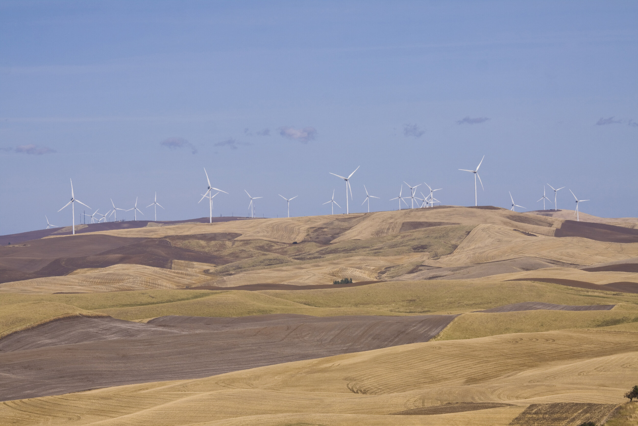
The case studied here corresponds to the Tehachapi Pass wind farm. The surface grid used to map the topography is displayed in the aerial photo, figure 1 below: the two HAWTs simulated are circled in red, the smaller circle denotes the front turbine. The distance between the rotor planes is 552m, rear rotor is elevated by 8m compared to front rotor.

Fig 1. Tehapachi pass wind farm aerial photo.
References: 1.USGS Geographical data, URL https://eerscmap.usgs.gov/uswtdb/viewer/#16.94/35.053542/-118.38226, 2021.
2.SRTM 30m Global 1 arc second V003, Global geographic elevation data, URL https://github.com/bopen/elevation, 2021.
Blade/Rotor actuator line model is based on NREL-1.7-103 1.5MW HAWT with rotor diameter D=103.7m, rotation speed of 5 rad/sec. The wind speed is U=8 m/s. The Turbine data is taken from NREL NREL-1.7-103 Wind Turbine Data, URL https://github.com/NREL/openfast-turbine-models.git, 2021
Results:
(i) All lengths are non-dimensionalized by the rotor radius, R=51.84m.
(ii) All velocities are non-dimensionalized by wind speed, U=8m/sec.
(iii) Time is non-dimensionalized by U/R.
(iv) Available wind power is non-dimensionalized by the power at the front rotor plane.
(v) Rotors are placed at (non-dimensional) X=x1 and X=x2.
(vi) All animations are recorded over the simulation (physical) time of 0 - 8 minutes (time steps 0 - 1610). Stills shown at T = 8 min.
(vii) Tubes are removed when reaching a distance of X=30. Larger distances were examined as well.
Flow dynamics, evolution in time of flow variables.
(i) Tubes: Snap shot of tubes (vorticity elements) at T = 8 min. The setting of Fig. 1 is rotated so that the flow wind direction aligns with the x-axis. The ground is colored according to the surface source distribution.

(ii) vorticity contours on XZ plane through center of both rotors. T=8 min.

(III) Velocity contours on a XY plane through the center of the front rotor.

(iv) Velocity contours & vectors at rear rotor computed at its elevation.

2. Turbulence Statistics
(i) Statistical equilibrium (convergence) data, top to bottom: # of tubes, splits, loop removed, far field tubes


(ii) Turbulence intensity contours on cross sections along the wakes: 1st section from left is front rotor plane, 6th section is rear rotor plane.

(iii) Available Wind Power P (P0=1) and Available Wind Power Gain (AWPG=(P-P0)/P0))

Comments on Results and Conclusions
•Using the actuator line model of the NREL-1p7-103 rotor blades, the simulation of turbulent rotor wake interactions of 2 WTs, placed in a real-life farm setting, produced high-resolution, consistent results that match the turbulent wake theory within the inviscid surface assumptions made here.
•The simulation results – ranging from turbulence intensity & turbulence kinetic energy, to available wind power, among others - allow for a better understanding of turbulent wakes evolution and interactions in different scenarios and subsequently for optimal design of HAWTs placement in a wind farm. This opens the door to the inclusion of additional physical phenomena so as to vastly improve the simulation results and avoid using empirical, ad-hoc, or calibration rules and data.
•It is shown that for wind turbine simulations, the Vorcat software requires only reliable rotor blade data for it to resolve the corresponding complex flow: in Vorcat, all turbulent flows are treated the same, no guesswork, a-priori knowledge of the solution, or calibration of parameters is required.