
Development of a Non-Diffusive CFD Wake Model for Rotor in Hover
Department of Defense, Naval Air Systems Command
Goals of the Study
The goal of this study is to demonstrate the feasibility of using the Vorcat code to accurately represent rotor wake dynamics, especially the tip vortex structure.
We performed a parametric study of a rotor downwash model under selected operating conditions, documented how the velocity and vorticity data changes along the wake for said conditions. In particular, we traced the tip vortex structure and evolution in time and compared with available data and theory.
Lastly, we performed simulations of hovering rotor over the geometry of the frigate shown below (unlike in the case of forward flight, discussed separately, this scenario was not tested in the wind tunnel)
Model frigate and grid


Rotor Model:
Based on the “Circulation Theory of Lift,” the circulation released from the rotor depends on the thrust, number of filaments released, rotor RPM, blade radius, and number of blades.
Also, the time step for advancing the blades is selected so as to allow for a minimum of 20 releases of vortex tubes from the rotor per revolution. This constraint is imposed so as to ensure highly resolved velocity fields at the rotor vicinity and beyond.
A real-time correction to the rotor model has been implemented as well but since it is the subject of a pending patent application it is not discussed herein.
Simulation Results

Hovering Rotor - No Solid Boundaries Vortex filaments: evolution of rotor wake

Normalized average inflow velocity for isolated hovering rotor
Flow Features - Isolated Rotor after 11.4 revolutions


Flow Features - Isolated Rotor


Hovering above the (stationary) frigate
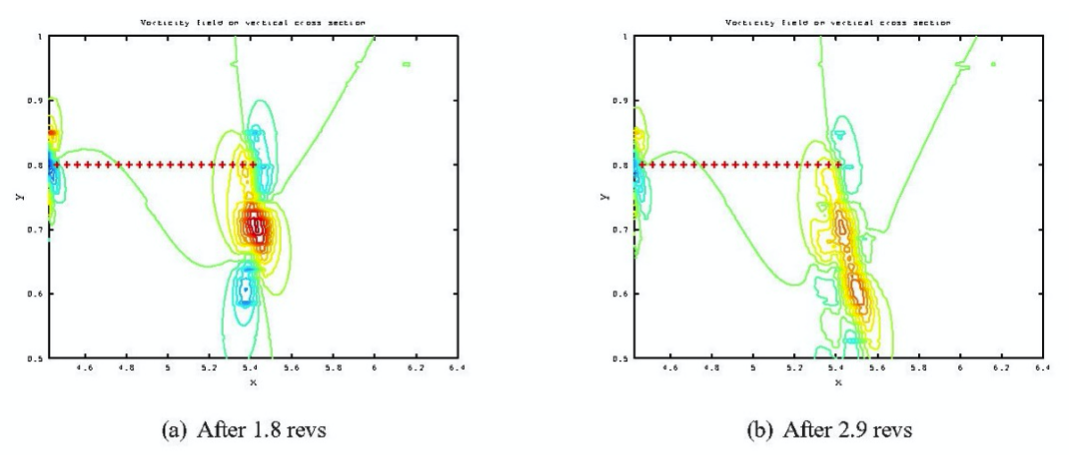
Vorticity field above frigate along its centerline


Streamwise velocity contours and vectors on a lateral cross section


Vorton field at T=0.279 after 6.3 revolutions


Normalized average inflow velocity at the rotor plane for rotor above frigate

Conclusions
It has been demonstrated that the vorticity shed from the blades of a hovering rotor form strong vortices that are transported downstream and break up into turbulence. The vorticity does not diffuse due to numerics and the vorton loop removal utilized in Vorcat simulations produces physically consistent results for this application as it does for numerous other applications tested in past studies.
For the applications tested here, it was found that:
Isolated hovering rotor: the improved, coupled rotor model produces inflow velocity which is 3-5% lower than the original model, due to rotor/rotor wake interactions. The average in-flow velocity at the rotor plane has been proven to be consistent with the numerical results. The setup and running of this code is simple and does not require ad-hoc tweaking, guesswork, or calibration.
Hovering rotor above a frigate: investigation of the results produced by both empirical rotor models employed here show that the underlying hypothesis of an averaged inflow velocity is not consistent with the actual solution and the configuration asymmetries must be taken into account. Similarly, solid boundaries must be represented as viscous surfaces so as to resolve accurately the vortex/solid interaction which leads to generation of additional vorticity. Similar to the earlier case study for NAVAIR, the Vorcat solution is consistent with physical tests, and the rotor wake vortices are not affected by numerical diffusion as is the case with other CFD technologies.
Computation speed: The solution of the experimental setting of case (2) above, took 18 CPU hours on 32 Blacklight processors to integrate to 430 time steps, at which time it produced 46M vortons (and it also solves the vorticity equations over 1M grid cells stacked in 11 layers). The Edison HPC system is roughly 1.6 times faster. Our code is undergoing major upgrade, which will accelerate execution time by 10X or more, in addition to improved scalability (subjects of pending Patent application).
The simulations accomplished in this study are made possible by the unique qualities of the numerical scheme that was applied and developed in this project. The minimal gridding requirements in which just a surface triangularization is necessary allows for rapid application of the technology to problems that involve complex surfaces. The capability for capturing the dynamics of shed vortical structure provides a good basis for simulating other important local phenomenon that is dependent upon rotor/rotor wake interaction, e.g., particle dispersion that may be of interest in other important applications.