
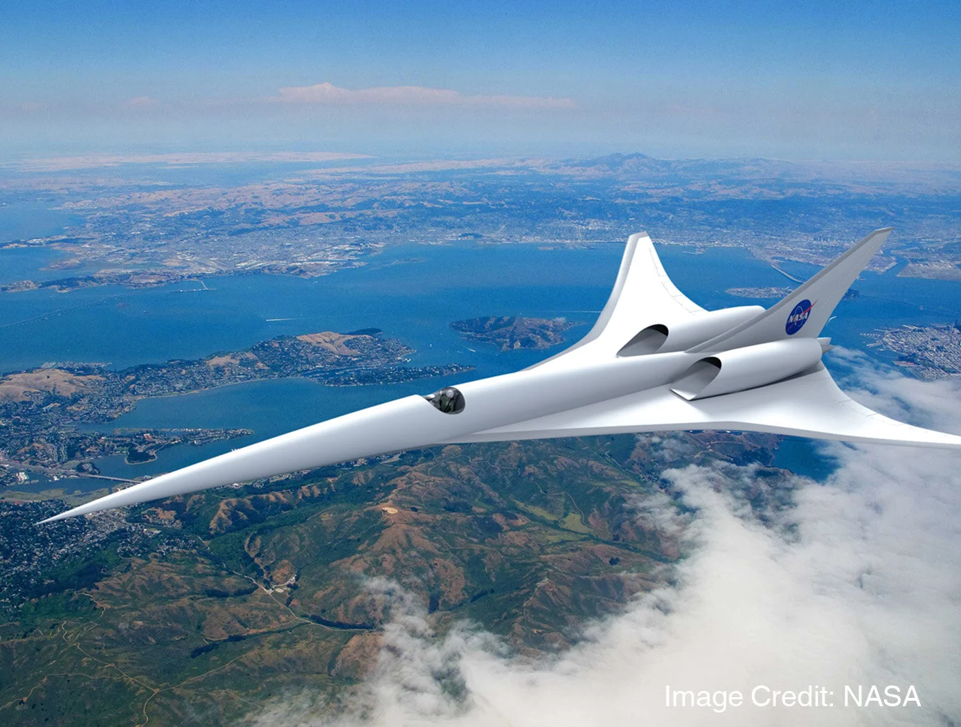
Analysis of Active Flow Control Concepts
National Aeronautics and Space Administration (NASA)
Goals of the Study
To demonstrate the feasibility of the Vorcat code for accurately simulating a benchmark synthetic jet flow.
Technical Objectives:
Utilize the Vorcat CFD software to:
Perform a numerical simulation of the synthetic jet scenario denoted CASE 3 of NASA Langley’s 2004 Workshop publication. Compare CFD results vs. experimental data.
Implement necessary algorithmic extensions and optimization of the code as required to meet Objective 1.
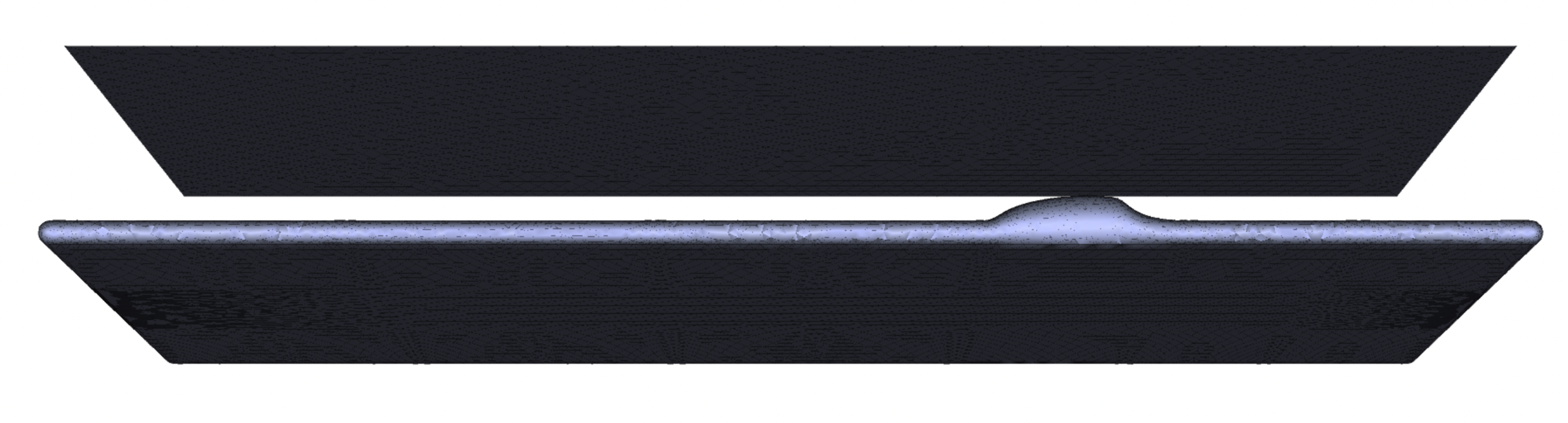
Case 3 – Model and Grid

Tested and Selected Parameters
Reynolds number (100K, 200K)
Grid resolution (75K - 142K surface triangles x 10 viscous layers)
Vorton cutoff distances (spanwise and downstream)
The selected configuration: Re=100K, 142K triangles, (1.4M cells) all surfaces are viscous except for top wall which is inviscid (cheaper to run).
Vorton cutoff at (i) rear end of plate, (ii) side (spanwise) borders of plate and, (iii) below the plate.
Length and velocity that are non-dimensional relative to chord length, c, and incoming velocity, Uin.
Important Run Parameters tested and selected
Vorton length (0.01 – 0.02)
Number of Sub-cycles - # of integrations in grid per one Langrangian step (10 – 40)
Vorton advection: 2nd order and 4th order Runge-Kutta (RK)
With and without Gaussian-hop-model diffusion
All other parameters – conventional.
For the first few hundred time steps, low resolution parameters were adequate. After that, as the flow evolves, the parameters were tightened:
Vorton length – 0.01-0.014, 20 sub-cycles, and 4th order RK.
Applying Gaussian-hop diffusion did not seem to make a difference.
Potential Flow Solution
Effect of sides on center of plate.
Convergence of potential flow solver (no-penetration BC)


Simulation Results
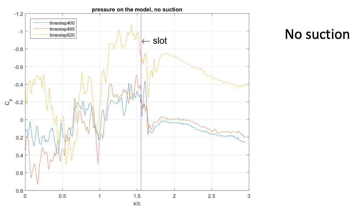
No Control
Rey = 100,000 (based on chord length)
T = 1.6
U = 1.0
Number of filaments = 7.9M
Number of tubes = 118M
RK2, vorton length=0.014
Constant Suction Control
Cµ = 0.24%
Applied at time step = 500 – 620 (T=1.63 – 1.80)
Simulation Results – Sample Vorton Field
Vorton (tube) field rendered by strength
Top - 10%, Bottom – 20%


BL velocity profiles (no control, RK4)

At experimental x = 2.17

at the slot
BL velocity profiles at slot, RK2 and downstream of slot

RK2

No control

downstream of slot

Suction control
Stream lines

No control

Suction Control
Pressure Computation
Post processing, using Uhlman’s (*) formulation,
For total Enthalpy, B
The pressure is obtained from the integral equation,

*Uhlman, J. S., Jr. (1992) ``An integral Equation Formulation of the Equations of Motion of an Incompressible Fluid,'' NUWC-NPT Technical Report 10,1086.
Transient Pressure Results

Skin Friction Coefficient, transient flow: Base flow vs. suction control

Mainframes (2016)
Computations performed on PSC/NSF HPE Apollo Bridges (http://www.psc.edu/index.php/bridges-deployment-plan) and NERSC/DOE Cray XC30 Edison and XC40 Cori (https://www.nersc.gov/users/computational-systems/edison/).
Summary
1. The Vorcat code has been extended and modified to allow the simulation of synthetic jet Case 3 with and without control (constant suction).
2. Vorcat has been applied to synthetic jet Case 3 with and without control (constant suction).
3. Run-parameters space that generates accurate and physical solutions has been established.
4. The results represent the transient solution of an impulsive start of the test flows that have not settled yet (“converged” in a statistical sense).
Conclusions
• The solution provides insight into the true physics of turbulent flow without utilizing approximations/averaging in model construction.
• The computational CPU required is proportional to the solution resolution.
• Time-dependent control mechanisms, e.g., turn-off and turn-on controls, moving boundaries, etc. – are straightforward.
• The only difficulty in obtaining highly-resolution solutions by employing Vorcat2.0 in its current state is computational speed:
Turn-around time on large, practical problems is measured in weeks if high-resolution solutions are required.
• The Vorcat3.0 version (under development) will be dramatically faster: we estimate a minimum 10X speedup via GPU computing and additional dramatic speedup due to improved scalability.